Wiring and photovoltaics systems
Dec 4, 2015. | By: Juan Pérez
In this post I will talk about the importance of proper wiring in electrical installations for safety and user confidence, the types there are, especially on sizing photovoltaic systems (you can get a quick picture in this infographic).
##Wiring importance
The safety of the electrical installation depends on many factors, increasing the risks to the age of the installation and user behavior in the use of electricity.
Wiring importance is essential to any electrical installation, regardless of the kind. Wires or conductors play an important role in the safety of the electrical installation for its impact on the presence of electrical accidents. The correct dimensioning of the sections and the proper selection of the types of electrical conductors to use, prevents electrical accidents such as fires and electrocutions.
##Types of wiring for each application
In electrical installations there are several ways in which you can distribute electricity and the conditions which must be submitted electrical wires. For this reason we have designed different wire types depending on where they are to be installed. In the table below you can see the features of wiring types or conductors which are used in electrical installations.
Wiring | ||||
Type | Material | Non-conducting | Disposition | Applications |
Air distribution | Copper | Polyethylene or PVC | Helically | Air BT, rush, general lighting |
Concentric | Soft copper | Polyvinyl chloride (PVC) | Concentrically | Single-phase electrical connections |
Multiconductor | Soft copper | Polyvinyl chloride (PVC) | Concentrically | Phase industrial equipment |
Duplex o SPT | Soft copper | Polyvinyl chloride (PVC) | Concentrically | small appliances |
SJT | Soft copper | Polyvinyl chloride (PVC) | Fluted or smooth | small appliances |
UF | Soft copper | Policloruro de vinilo (PVC) | Parallel | Power circuits and industrial lighting |
##Parameters to consider in wiring
To ensure that our installation is safe and can trust her, wires or conductors must meet some essential requirements for future use. What are the following:
- Load or consumption: this defines what supports current electrical conductor, there are in KW, HP, KVA or AMP. Loads can be very diverse, from a house to an electric motor. You must consider whether the load is connected to a single or three phase system, depending on the type, the consumption can be reduced.
- Load distance: the resistance of the electrical conductors depends on three factors, two geometric and the other by chemical matter; I’m talking about the cross-sectional area of the conductor or the length and resistivity. The second is a factor that defines the voltage drop across power wires. This is for a very simple reason, conductor length is directly proportional to its resistance. Therefore, the closer you are the best freight.
- Ambient temperature: depending on the requirements of the installation, there will be areas at low or high temperature. The environment where the wire is, will determine which stream without this generates losses in the conductor. Environments with very high temperatures, requires wires to consume more energy. This caused by the variation in the coefficient of electrical resistivity. With increasing temperature, the resistivity increases, it makes resistance increase too and therefore the voltage drop, making more power consumption than it can carry.
- Grouping factor: electrical conductors generate heat as it flows through this electric current. These drivers are designed for electrical channels or pipes, to be grouped in the same pipe and all generating heat to a certain extent, this cause all the heat is concentrated in that space. Increasing the resistivity of the conductors and generating greater losses. This factor defines the actual flow that can carry a driver, depending on the number of wires where this staying.
- Type of insulation: heat transfer depends on the type of material that comes between two media with different temperature. If you check in tables ampacities, drivers can see the comparison of why the same wire can drive different currents. This information tells you that the insulation affects the current that can support the driver, and must take into account the environment where it will be installed.
- Voltage drop out: the distance, the charge to be installed, the current through clustering factor, the voltage level, type of delivery system, these factors determine the voltage drop across power lines. The rule is that it must not exceed 2% for main feeders, and 3% for feeder branch circuits. This is a total of 5% for the entire installation.
##Sizing of a photovoltaic system wiring
The dimensioning of an installation is the key part for the design and implementation of the facility. First of all you must always follow a process of good design calculations for our facility, this is where the good sized fits the characteristics specified.
As this post is about the wiring, I will focus only on the sizing of the wiring referring to a photovoltaic installation. For wiring sizing we must follow this two standards.
- Voltage drop out: the current flow through the conductors, results in a loss of power carried by the wire, and a voltage drop or difference between the voltages at the origin and end of the pipe. This voltage drop out should be less than the limits set by the Regulation in each part of the installation, in order to ensure the operation of the receptors powered by the wires. This standard is often the determinant when the lines are long length, for example, individual leads that feed the top floors in a building of a certain height.
- Thermal standard: the temperature of cable conductor, working at full load and at steady state, should not exceed at any time the maximum permissible temperature assigned to the materials used for cable insulation. This temperature is specified in the particular rules of the cables and it’s usually 70 ºC for thermoplastic insulation and 90 ºC for thermosetting insulation.
In order to calculate this standards in an easy way i have created a tool for wiring sizing in low tension installations.
To choose our driver we must previously calculate the intensity and power of our line, everything depends on the design that we will perform. Once completed, we can certainly choose our driver. More information.
##Most used wires in photovoltaics
In the world of photovoltaics as well as electrical installations, numerous types of drivers are used. Here I will mention the most commonly used in photovoltaic systems.
Type | Description |
wire VV-K (norm UNE21123-1) | wire rated voltage 0.6 / 1 kV, with Class 5 copper conductor (-K), insulation and covered with polyvinyl chloride (VV) |
wire RV-K (norm UNE 21123-2) | wire rated voltage 0.6 / 1 kV, with Class 5 copper conductor (-K), reticulated polyethylene insulation (R) and covered with polyvinyl chloride (V) |
wire RZ1-K(AS) (norm UNE 21123-4) | wire rated voltage 0.6 / 1 kV, with Class 5 copper conductor (-K), reticulated polyethylene insulation (R) and cover thermoplastic compound with low smoke and corrosive gases |
##Conclusion
In conclusion I can say that the subject matter in this post is something important to protect and care our installation as possible. Because if the maintenance is up to date, we are talking about we save an investment in maintaining our facility periodically, however, this does not mean that if we get good materials, in this case high quality cables, we forget about maintenance. However, the use of high quality materials, will help us to protect our lives and our environment. In the world of photovoltaic energy we know two types of installations, isolated and connected to the network. Both have their advantages and disadvantages, all depending on the purpose of each facility, but what must be made clear is that one facility or another must have a certain quality materials that guarantees good performance and a good security.
Subscribe
Subscribe via RSS.
Recent Posts
-
 Posted on 10 Feb 2023
-
 Posted on 26 Jan 2023
-
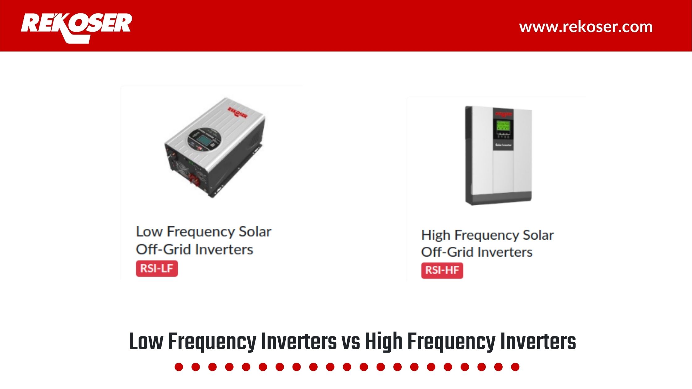
Differences between Low Frequency (LF) Inverters and High Frequency (HF) Inverters
Posted on 25 Nov 2020 -
Whitewall Energy presents the new Rekoser batteries catalog for 2016
Posted on 07 Apr 2016